Making a NPR Shader in Blender
This article is the result of my first attempt at making an NPR shader inside Blender.
I first tried to play around the shading node system as well as the post processing effects like Ambient Occlusion or Bloom and test various things. As I would like to focus on “real-time” rendering, I tested everything with the EEVEE rendering engine. I also looked at many videos and works that have been done inside Blender for NPR.
If you are interested in the subject, you can take a look at (or even join) the Blender NPR community and also check out the Lightning Boy Studio youtube channel, there are many resources for that field.
In this article, I am going to describe a simple version of a Blender shader NPR that I built. Of course, I took inspiration from what is available on the Internet and also tried to propose my own vision. It is very far from perfect but I hope it will give you a basic understanding in order to start exploring NPR on your own.
Shader Structure
The shader is represented as a node group which itself is divided into several groups that correspond to light contributions. More precisely, this NPR shader light contributions are divided into 5 components: Diffuse, Specular, Ambient occlusion, Sub-Surface Scattering (SSS) and Emission. Furthermore, I also include Rim light and Outline contributions which are heavily present in NPR shaders.
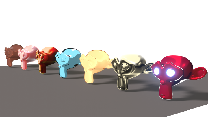
First let me tease the kind of results you can obtain with this shader.
model: Clare by ruslik85 on Sketchfab
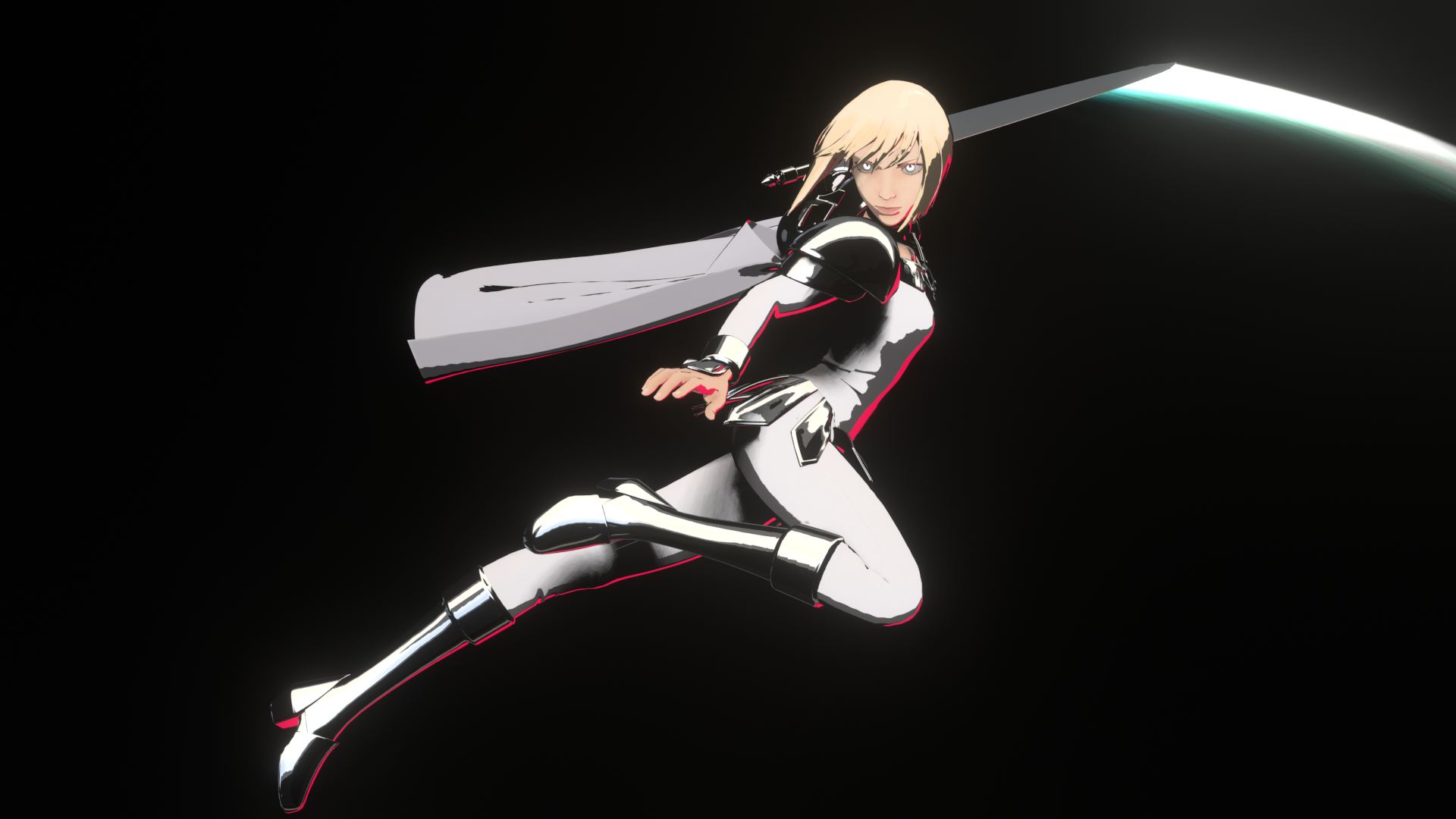
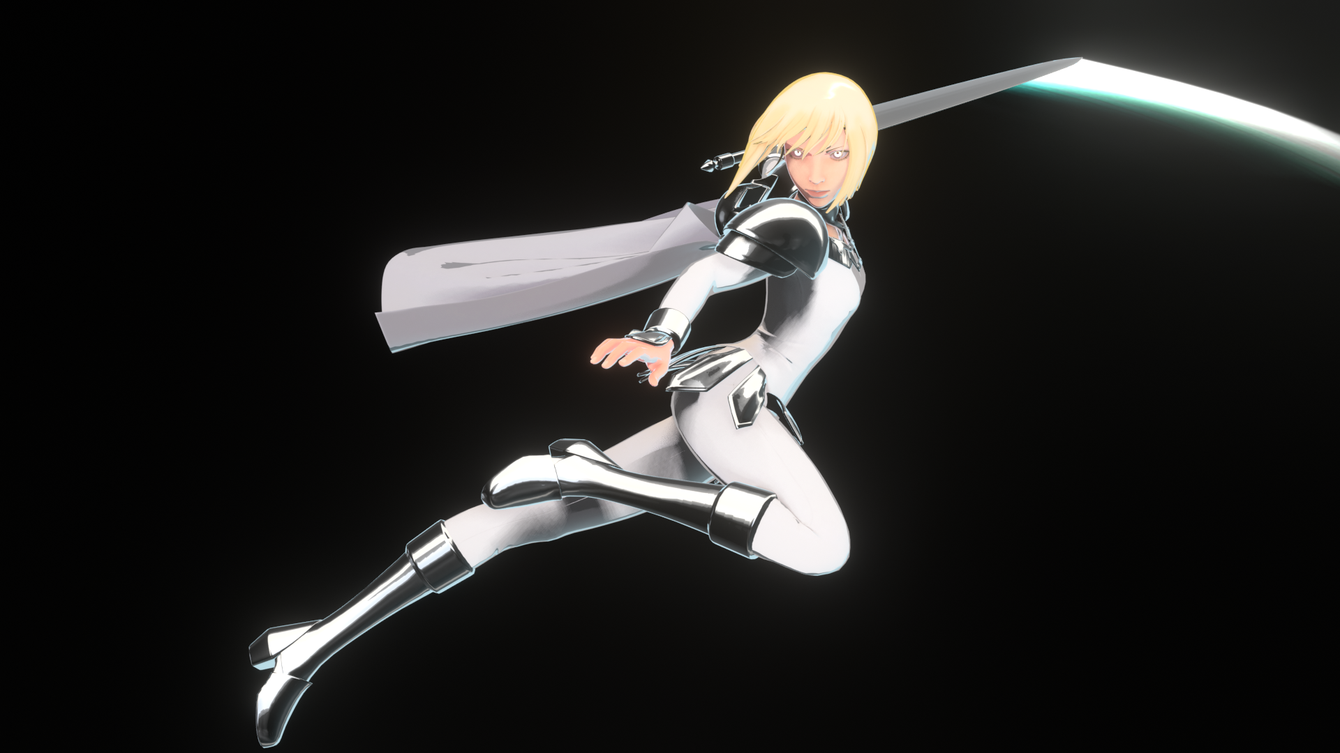
As you can see the range of rendering styles can vary from very cartoonish shading to more realistic results. Below, you can notice the difference compared to a more realistic look using the principled Shader (model: Ruby Rose by theStoff on Sketchfab) :
| Realistic | Cartoon |
|---|---|
The main tool to make such variations is to use color ramps to tweak the output of base shaders, like the Diffuse or Glossy (Specular) shaders. There is more to it of course, and we will go into details in the next sections.
As you can see, the NPR look is more contrasted and “flashier” than the realistic look. It also while masks details at the same time. However, thanks to effects like Outline and Rim Light, we are also able to make relevant parts of the model (like the silhouettes) stand out. This is especially useful to improve the perception of characters’ poses and their motion.
This simple Blender NPR shader is build as a node group that can be tweaked with numerous parameters:

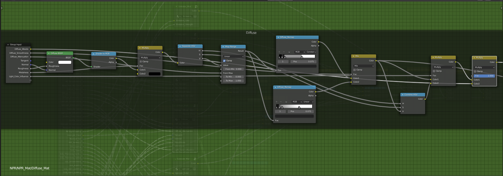
And here is an overview of what the inside node group looks like:
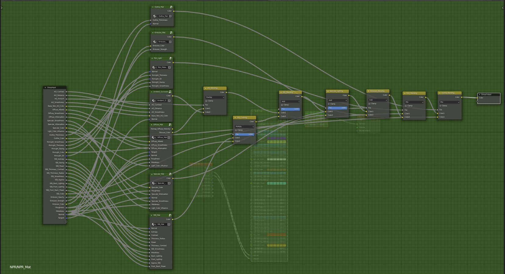
This node group is itself divided into 7 sub-groups, each corresponding to different light contributions. We then blend them together by choosing an appropriate blending operation. Each of these contributions will be detailed in its own section as well as their blending.
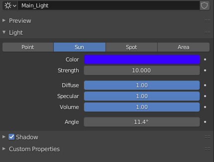
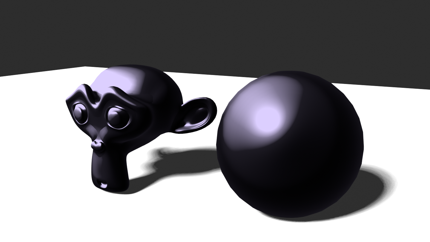
Let’s first dig into each component independently for a scene containing a plane, a sphere, Suzanne and a sun light.
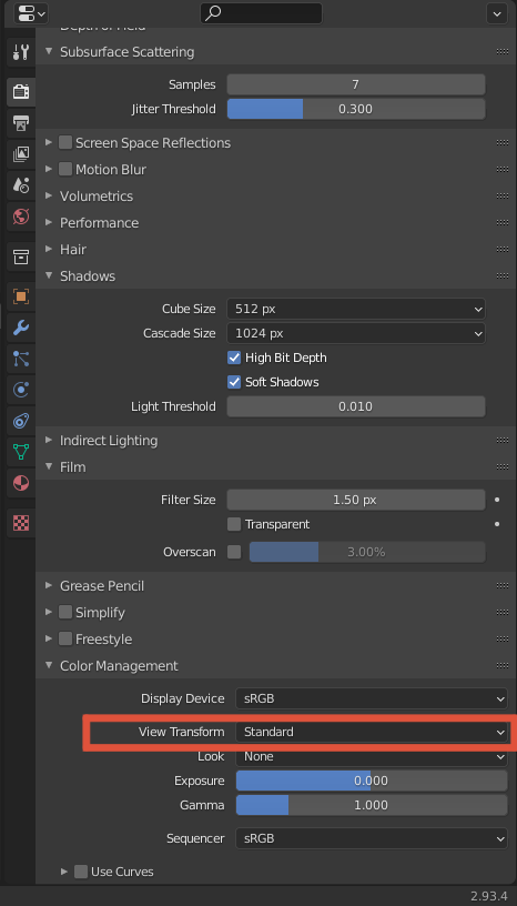
NOTE: Before going further, it is important to switch the color management to Standard in the Render Properties panel as we want to control our color output precisely
Diffuse Component
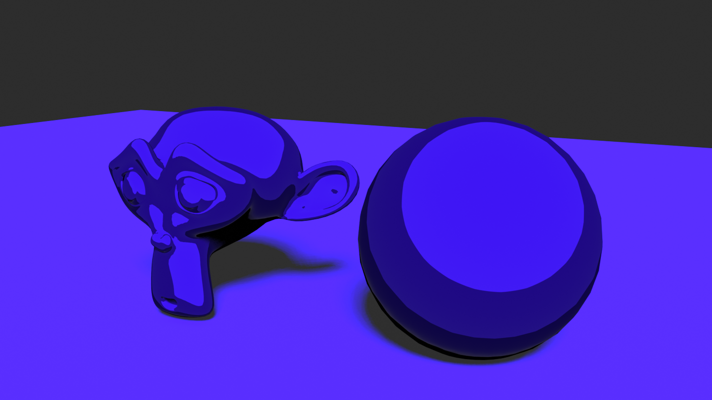
The diffuse component represents the amount of light re-emitted by the surface after receiving incoming light, here coming from lamps. This amount can be obtained using the Diffuse BRDF node which computes a physically based diffusion.
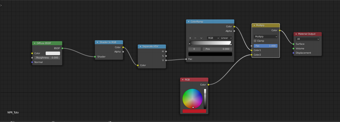
As our objective is to produce stylized results, we would like to tweak this output and have some artistic control over it. Here comes into play the basic node that everyone uses in the NPR community, namely the ShaderToRGB Node. Indeed, this magic node converts the shader output into a color (works only for EEVEE at the time I write this article) and lets us tweak this output color.
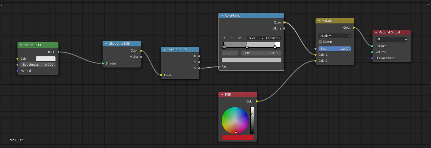
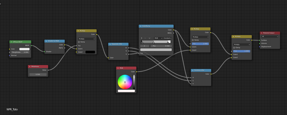
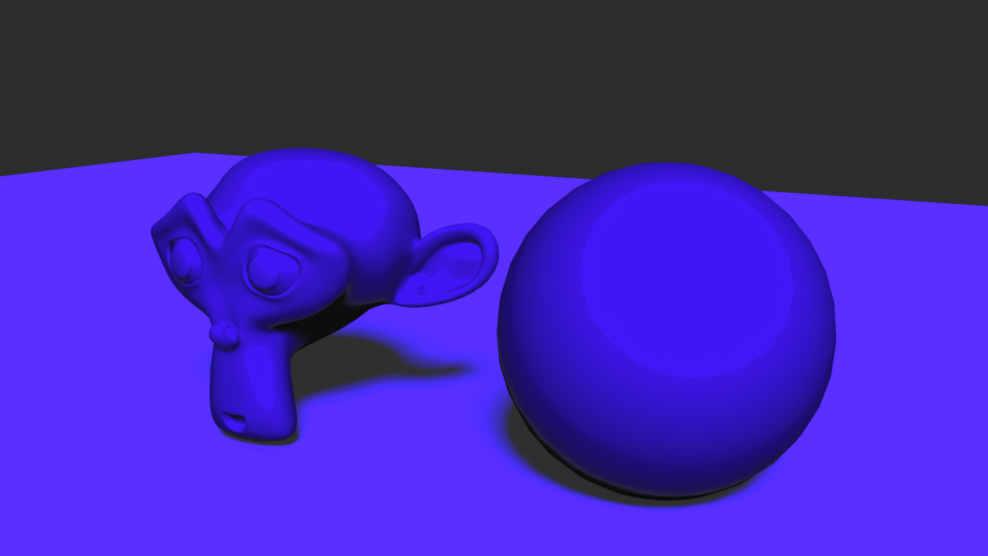
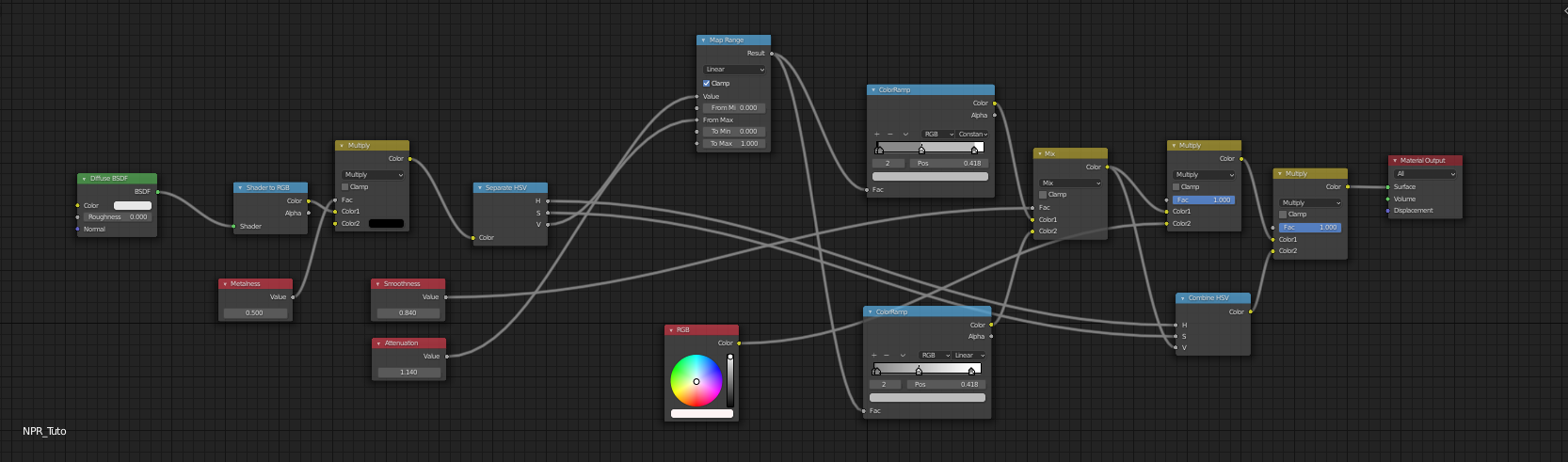
One convenient way of tweaking this color is to use a Color Ramp which allows us to remap an input color into an interpolated color computed from parameterized colors spread into a $ [0:1] $ range. The control offered by color ramps is pretty intuitive and thus, it makes a good candidate for us to use in our stylization process. To tweak the diffuse component we will proceed the following way: first set the albedo of the surface as pure white in the diffuse shader and plug the output color (after ShaderToRGB) as the input of a ColorRamp. Then we can modify the color ramp content to stylize the diffuse contribution. And finally, we can get back the color of the surface we actually want (diffuse albedo) by multiplying the output of the color ramp with the surface color.
NOTE: Note that I use a Separate HSV node right after ShaderToRGB to use the value of the input color as it is the only attribute that interests us.

That’s a good start, but several questions need to be answered: how do we modify the color ramp to get a stylized result ? What about metallic materials ? How to get back the influence of the incoming light color which is discarded with our current setup ?
Playing with color ramps
We were able to get the light contribution of the Diffuse component inside a color ramp, it is now time to play with it in order to stylize this contribution. To do it properly, we first need to understand what is happening inside the Diffuse node and think about how we can get closer to a stylized result like we can see in cartoons/anime.
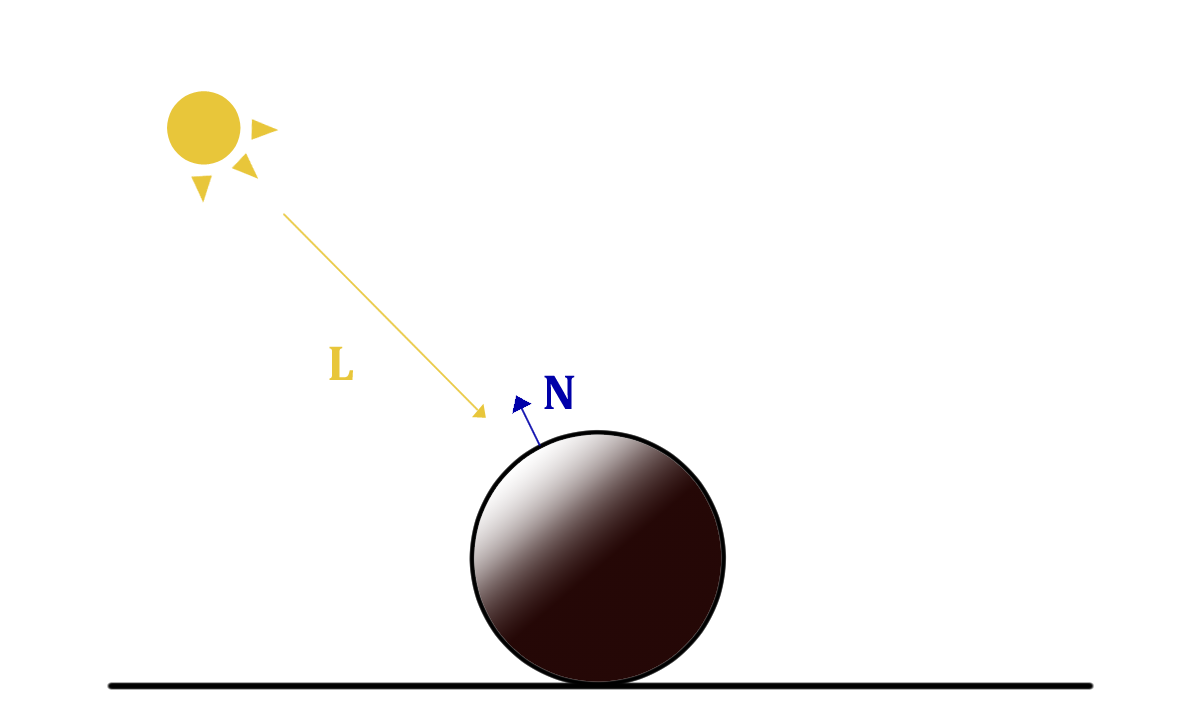
To put it simply, the Diffusion or the light re-emitted by the surface of an object hit by light, depends on the surface orientation, referred as the normal $N$, with respect to the incoming direction of the light $L$. If the surface faces the incoming light direction it will re-emit more light. This can be simply modeled using a dot product between L and N of the surface.
$$ D_{iffuse} \approx max(-L \cdot N,0) $$
This is the basic computation that occurs inside the Diffuse node (it is a little bit more complicated in practice but let’s keep it simple in this tutorial). For smooth surfaces like humanoid characters, this Diffuse contribution also varies in a smooth fashion alongside the model, which is not the case when you look at cartoons/anime. Usually you get one, two or three grading levels with abrupt changes.
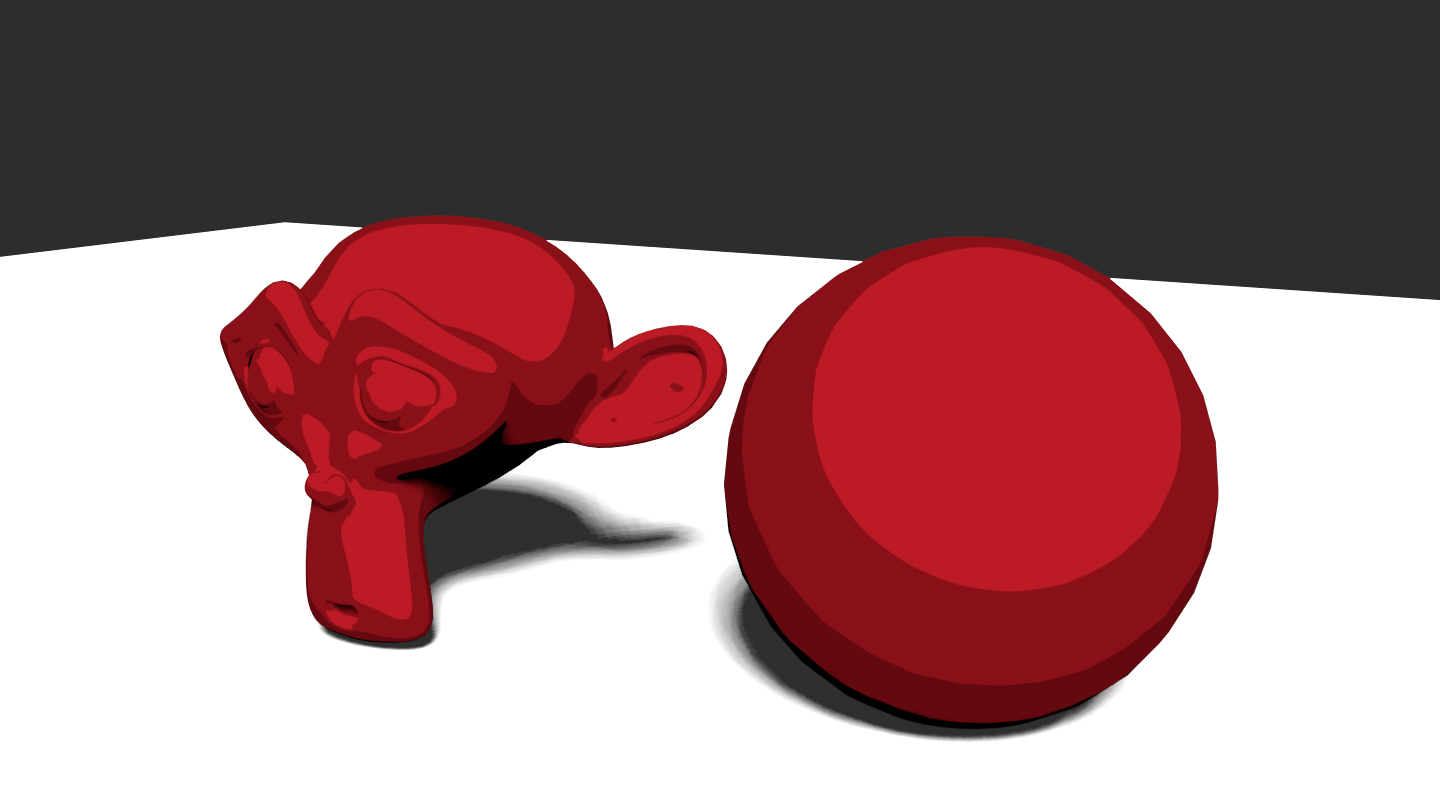
To get these results with the color ramp, we simply have to add levels to the ramp (press the ‘+’ button inside the ramp) and change the interpolation mode to constant, restraining the number of light levels diffused by the model to a fixed number.

Et voila ! you get a cartoonish/anime shading. You are free to tweak the levels at your own convenience as well as to use a smoother interpolation and even mix the discrete and smooth Diffusion, like I suggest in the final version of the Diffuse shader.
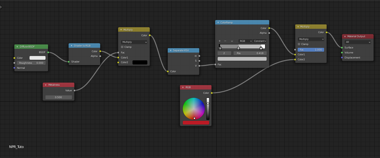
Metallic Diffusion ?
As you probably guess there is something to take into account with metallic materials regarding Diffusion. Indeed, something to know is that metallic materials do not diffuse light, only absorbing and reflecting it.
That’s why we took it into consideration by multiplying the result of the diffusion with $ 1 - metalness $.
Light Color Influence
Using our current node configuration, you can notice that changing the light color has no effect on the shading of our objects.
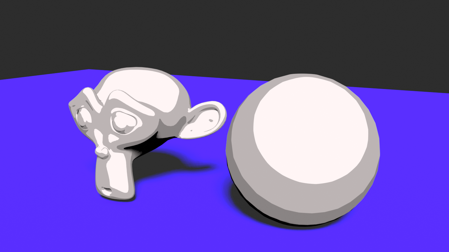
And this is due to the fact that we use the output of the gray scaled color ramp as the Diffuse light contribution. And so, light color influence is something we lost from the Diffuse BSDF that takes this factor into account. The question is how to get it back ? The answer is quite simple. As we already recover the light intensity of our shading (value of the HSV node) we just have to get back the hue and saturation resulting from a multiplication between the object color and the light color.
Smoothness and Responsiveness
It is also possible to give more artistic control to the Diffuse component, and this is something we will also use for the Specular contribution.
First, it is very handy to add a smoothness control to your Diffuse shading. And this can be done easily by adding a second color ramp with a linear interpolation this time, and blend it with the previous color ramp we built using a Mix Color node and a smoothness parameter.
Secondly, it can also be useful to add a control that tweaks the amount of light re-emitted using a Map range node that maps $ [a : b] $ to $ [c : d] $. Here, we use an attenuation parameter that we plug as $b$ so that $ [0:b] $ gets mapped into $ [0:1] $, thus the higher $b$ is the less light will be re-emitted.
Specular Component
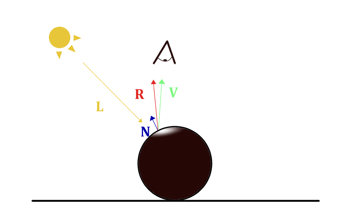
The Specular component represents the amount of incoming light that is reflected by the object surface. One simple way of formulating its contribution is : from the camera point of view, how well does it see the light source reflected on the object ?
The simplest model describing this contribution has been introduced by Phong, and simply look at the dot product between the reflected light vector $ R = reflect(L,N) $ and the view vector $ V $.
$$ S_{pecular} \approx R \cdot V $$
Inside Blender, computations are more complicated as it relies on physically-based algorithms and I invite you to take a look at my Physically-Based Rendering tutorial if you want to know more about it.
The way we will implement this component is highly similar to what we did for the Diffuse component and thus I will not detail everything in this section.
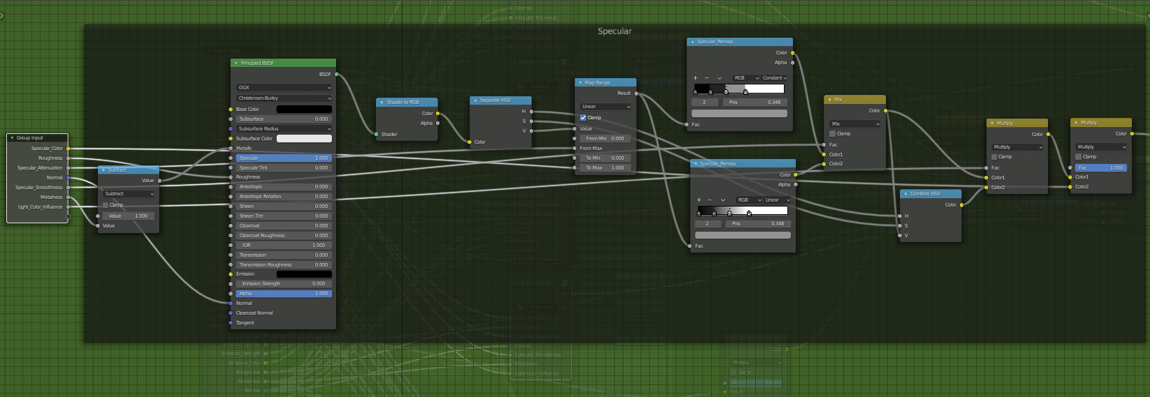
The first thing to note is that I used the Principled BRDF node to get the specular component as the other nodes don’t provide support for metallic materials. As we are only interested in the Specular component here, I put a perfectly black color for the base color, so that we remove the Diffuse contribution provided by the Principled BRDF node. I also put the specular parameter at $1$ and plugged in the roughness parameter that plays a big role for that contribution. It is also important to notice that the metallness used is actually 1 minus the metalness and this is for stylization purposes.
The rest of the Specular node group is exactly the same as the Diffuse component. We sample the intensity (or value) of the Specular contribution using color ramps, possibly attenuating it beforehand, and mix the result with the specular color and the light color influence.
NOTE: A small note for metallic materials. To enhance the look of metallic materials, you might use an environment map for the World material to get more reflections and thus a more believable look.
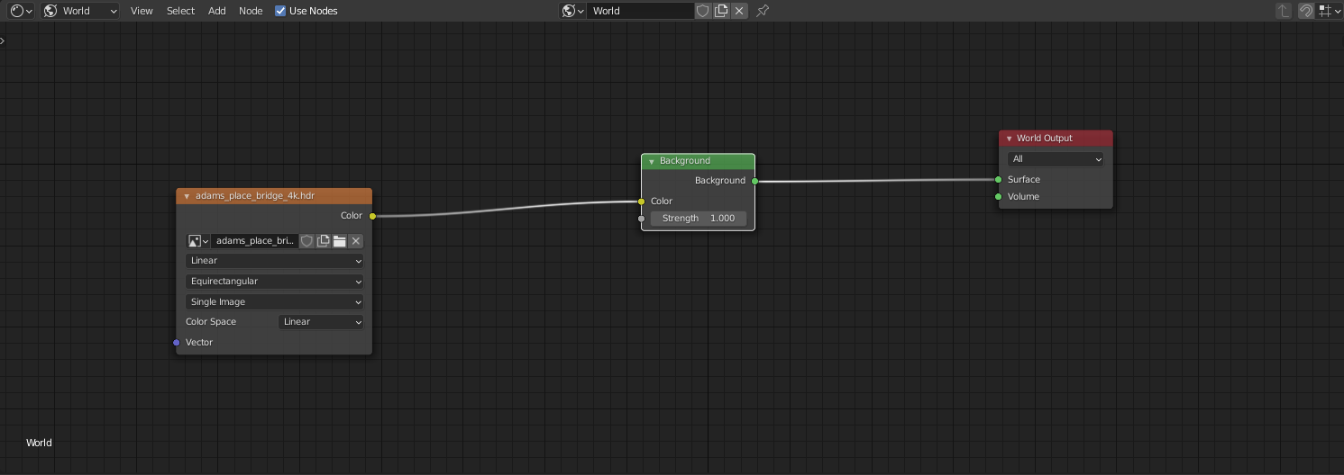
| No Env Map | Env Map on |
|---|---|
Ambient Occlusion
Ambient Occlusion (AO) is actually not a light contribution but more like a shadow contribution. It describes the area of the scene where light rays are less likely to hit. This is especially the case of corners and creases and it is quite noticeable if you look at your room for instance.
Ambient occlusion greatly enhances the realism of real-time renders and is something that artists are aware of when drawing and painting. In our case, we would like to use it to give more contrast and color variation to our renders.
The first thing to do when using EEVEE, is to enable Ambient Occlusion in the Render Properties tab.
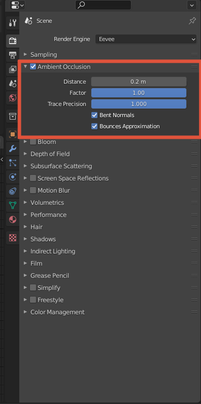
There are a couple of parameters like the Distance, Factor and Trace Precision as well as Bents Normals and Bounces Approximation. I won’t go into details on how Ambient Occlusion is computed but for our purpose let’s keep Factor and Trace Precision at 1 and enable Bents Normals and Bounces Approximation. The distance in this tab is not relevant and will be tweakable from the Ambient Occlusion node directly.
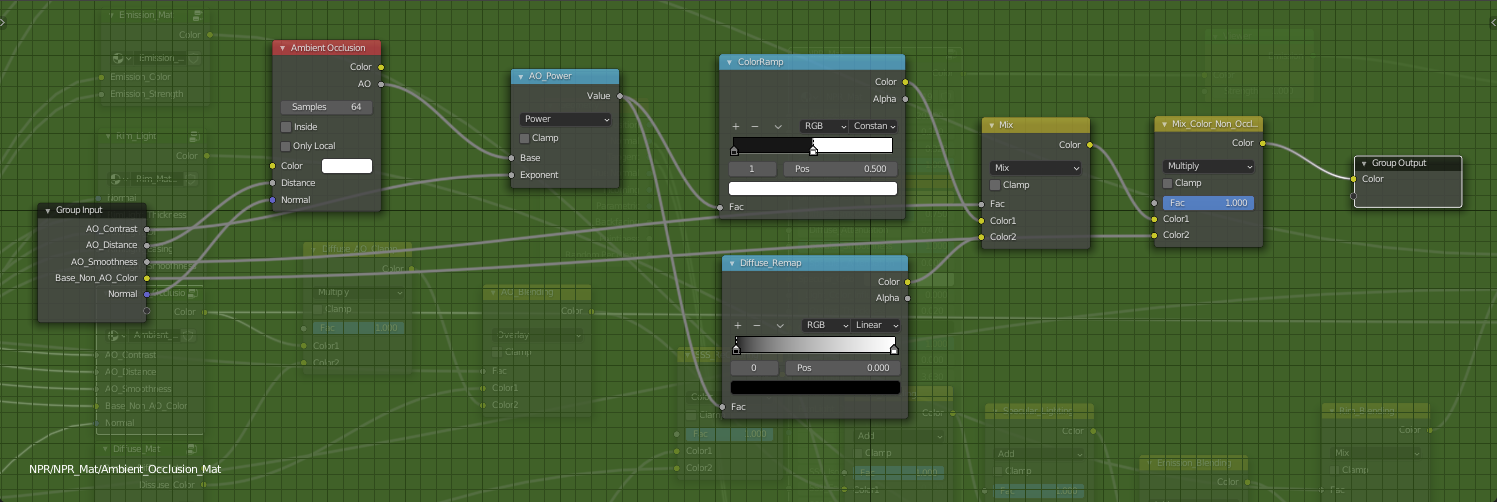
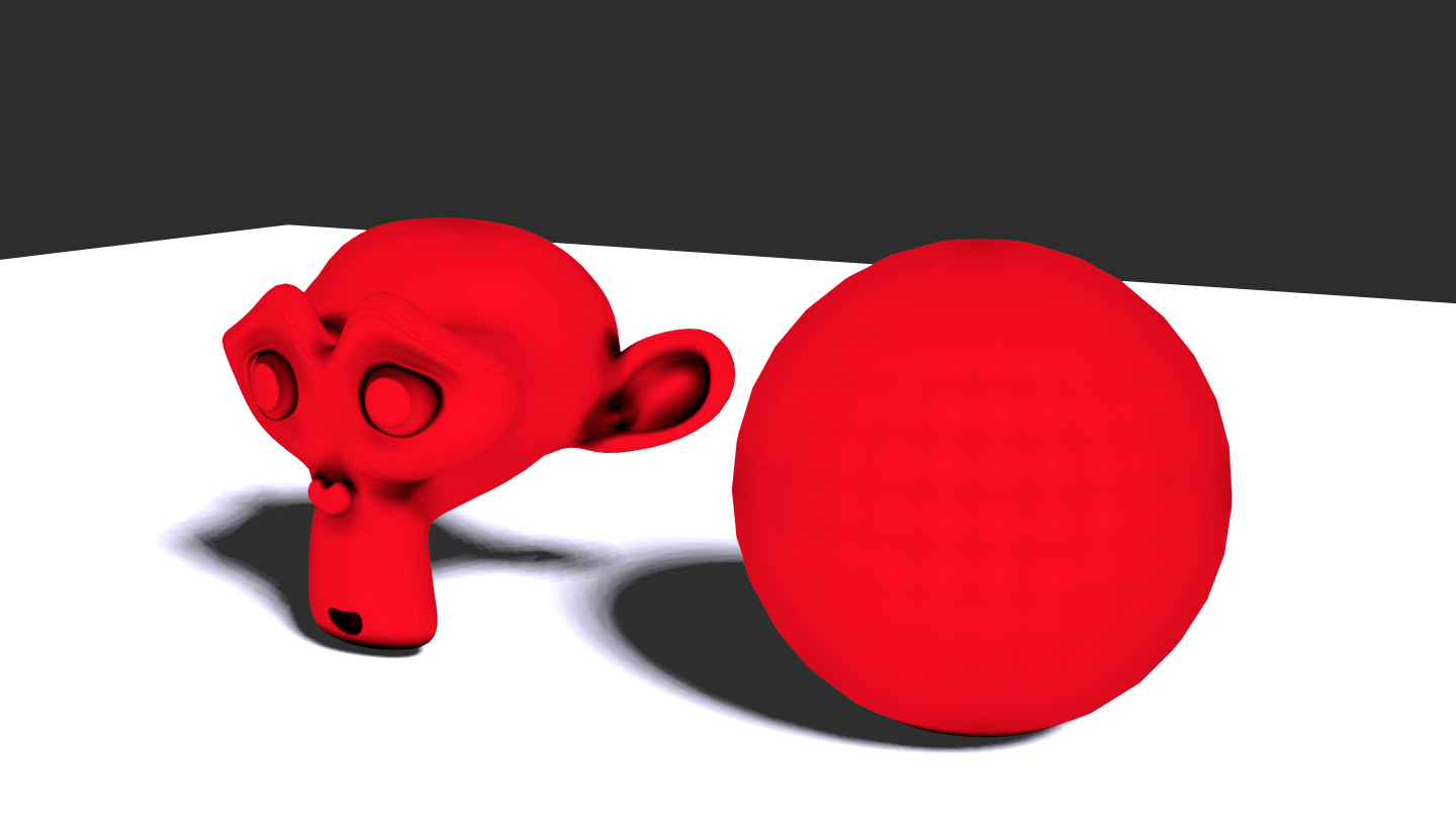
Like for Diffusion and Specular Reflexion, we use a color ramp to limit the number of grayscale levels AO can contribute to. Notice that I limited AO to two levels for the cartoonish/anime shading as it is often more subtle than the previous components.
You will also have to adjust the Distance parameter depending on the scale of your model, especially for small and large models. In the first case your model might be fully occluded while in the second case you might not notice any occlusion if you don’t tune this parameter carefully.
I also added a Math power node to tweak the contrast of AO and give it more importance.
Finally, to further increase the color contrast, we assign a color to the non occluded areas with a Multiply node.
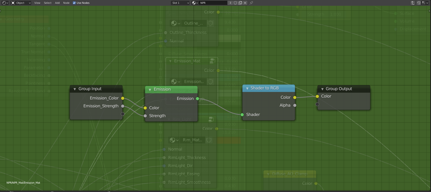
Emission Component
The emissive contribution is the easiest to take into account as Blender already does all the work for us with the Emissive shader.
However, it is important to note that when using EEVEE and real-time renderers, you have to enable Bloom to get a greater impact.
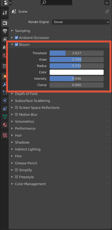
It is a post-processing effect that highlights the brightest parts of your scene which is the case of emissive materials. This is something widely used in video games to make fire, lasers, lamps and other special effects to stand out. As you can see, there are also few parameters to tune the Bloom effect. You might want to tweak the Threshold parameter that determines when a given color intensity (value) is considered as bright.
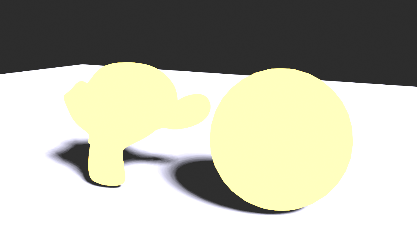
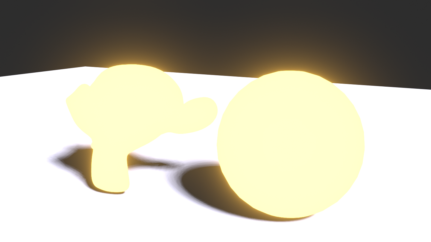
Notice the difference when Bloom is enabled.
| No Bloom | Bloom On |
|---|---|
 |
 |
Currently it is quite costly to handle emissive materials as light sources in a real-time fashion. Handling emissive materials like path tracers (Cycles in Blender) might change in the future with real time ray tracing being faster and more optimized.
Rim Light and Outline
Rim lighting and Outline are tools used by artists to better depict the contours and the pose of characters. They can also be used to set a specific mood and to enhance the perception of motion.
Extracting the contours
There are plenty of techniques to get the contours of a 3D model and draw art lines on top of it. There are pros and cons for each technique, but state-of-the-art methods tend to give a lot of freedom with computational costs that get shorter and shorter. Benard et al. made a survey summarizing many existing methods to draw art lines on top of 3D models.
In this tutorial, I described the simplest approach which is far from being perfect and you might want to use other methods like the inverted hull, at least for the outline.
The simplest way of getting the contours is to use the dot product between the view direction $ V $ and the normal $ N $. Indeed, one way of defining parts of a 3D model that are near the silhouette is to look at where this dot product is near zero, or formulated differently, where the normal of the surface is orthogonal to the view direction.
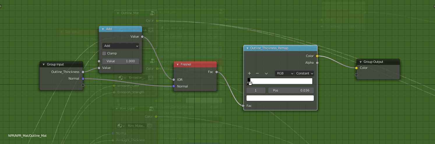
Outline
There is an easy way to get this dot product in Blender within one node, namely the Fresnel node. It takes into account an index of refraction which is a fundamental parameter to determine the amount of light that goes through the object, which also tells us the amount of light that gets reflected as its complementary. This amount of light being reflected is directly linked to the dot product between the view direction $ V $ and the normal $ N $. And so, to get the Outline, we can use the output of the Fresnel node and threshold it with a color ramp like we did for the other components.
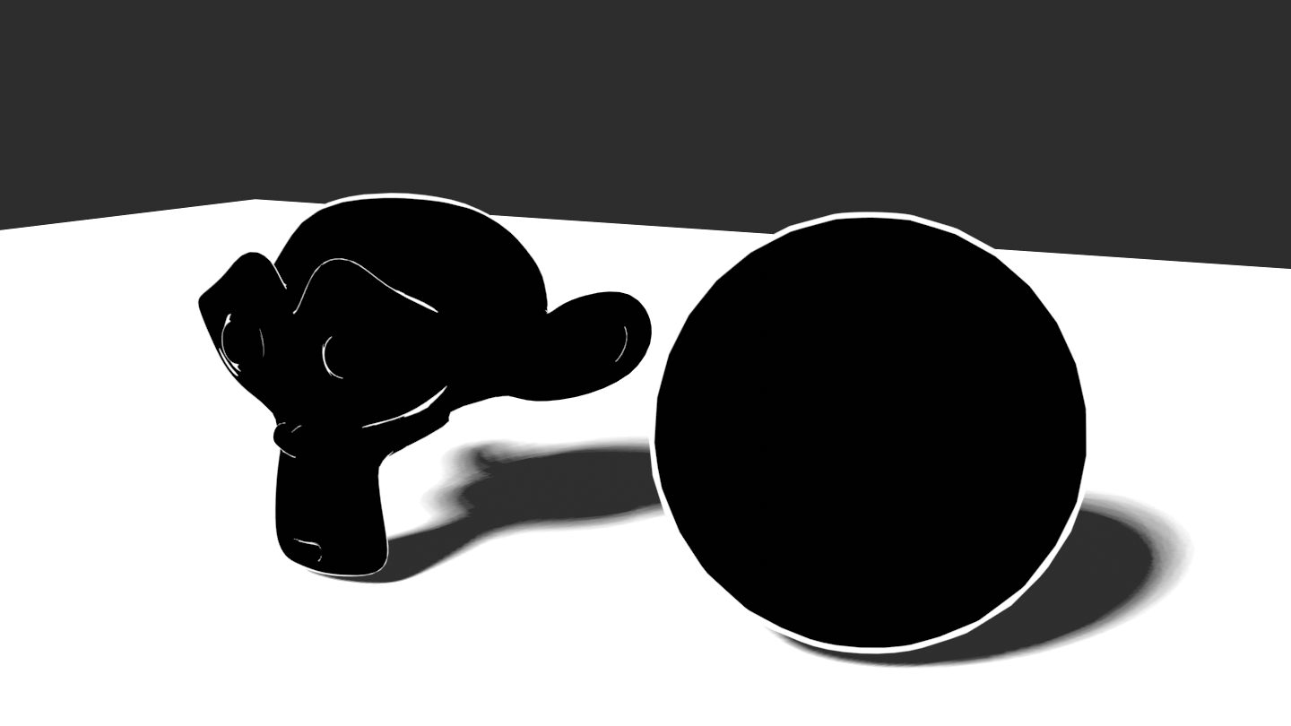
Rim light
Rim Light is also referred as a backlight that highlights the full silhouette or only one part of it.
To achieve this effect with 3D geometry, we can also compute the dot product between the normal $ N $ and the camera view $ V $ to get the silhouette and use color ramps to tweak its values. This time I intentionally computed the dot product using Vector Math nodes.
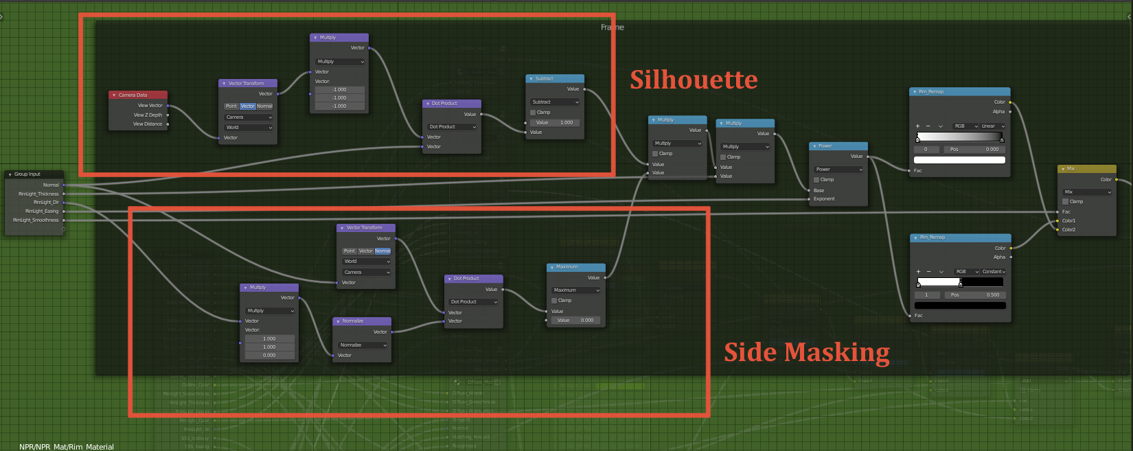
We also need to limit the highlighted area to one side of the model (Side Masking). More precisely, we have to think in view space to correctly achieve this effect. Therefore, we convert the normal into view space using the Transform node. Basically what we want is to limit the silhouette lighting where the view space normal is aligned with a desired rim light direction. Computing an alignment with a vector is equivalent to compute the dot product between the normal and the Rim light direction.
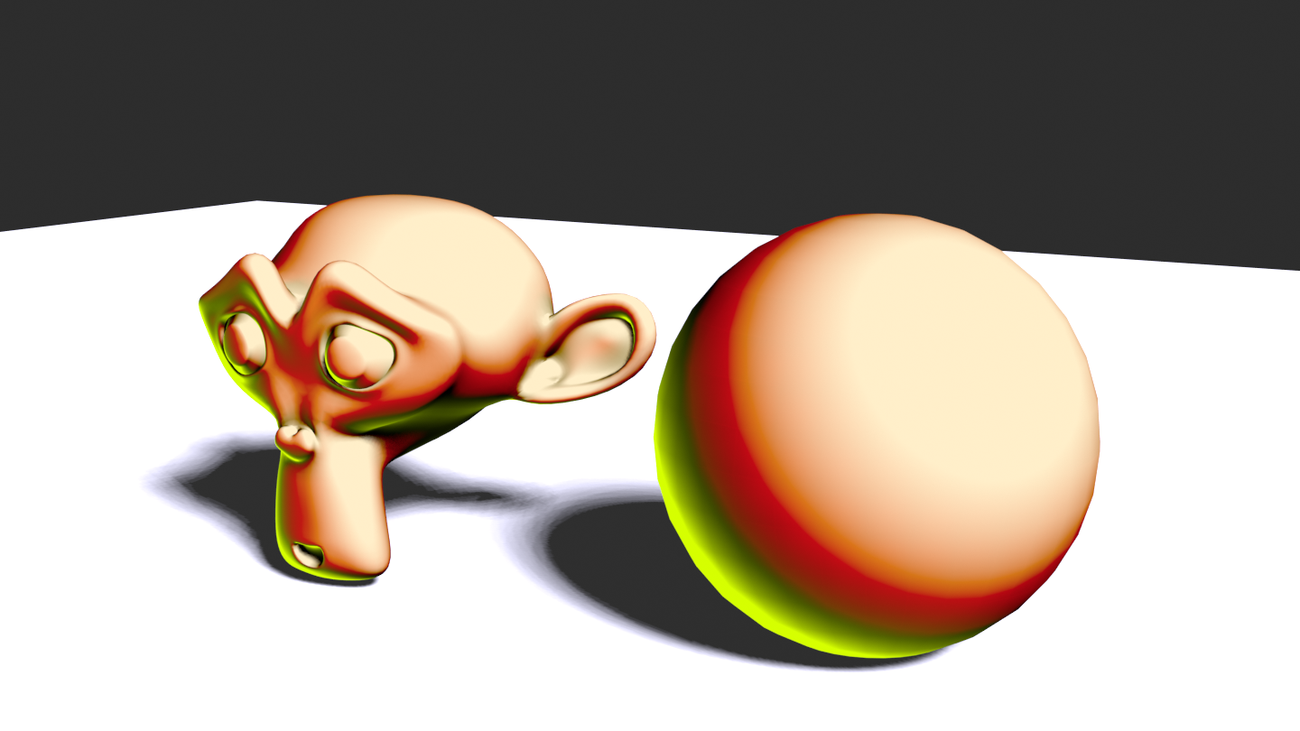
And that’s it, using this trick we can highlight one side of the silhouette and mask the other side.
NOTE: Note that this Rim light direction is encoded as a 3D vector as Blender only supports them, but in practice we do not use the Z coordinate, hence the Vector Multiplication node.
As a final touch, like precedently, we can use color ramps to sharpen or soften the Rim Light depending on the style you want to convey.
Sub-Surface Scaterring
Sub-Surface Scattering (SSS) is one of the most difficult contributions to handle as it is also a more complex phenomena. It corresponds to light rays that completely traverse an opaque medium, like your body, and that reaches your eye. One common example given to behold this phenomena is to place your hand between you and the sun and look at the space between your fingers, you will notice a reddish color at the silhouette of your hand. This is the light going through a thin opaque medium that is your skin.
Although it is a quite common phenomena, it is also very difficult to achieve in a real-time fashion and for this tutorial we will use the approximation proposed by Alan Zucconi (based on a GDC talk) to achieve our NPR SSS inside Blender. Note that we will not use the SSS shader provided by Blender as the method proposed by Alan Zucconi offers more expressiveness and better artistic control. We will also extend this approach by adding two additional contributions.
Approximated SSS
In this section, I will mostly paraphrase the tutorial of Alan Zucconi, I will skip few details and explain how to implement it inside Blender.
Like I mentioned above, SSS is a complex phenomenon where light rays go through the surface and are also deviated from their incoming direction.
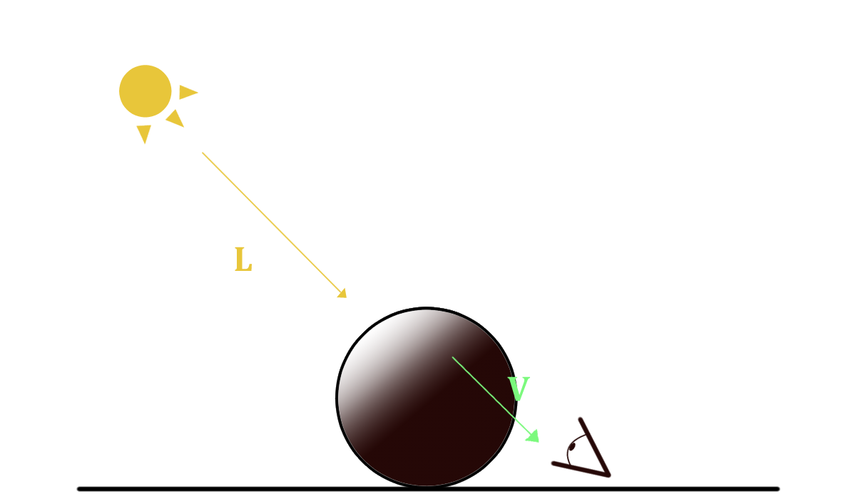
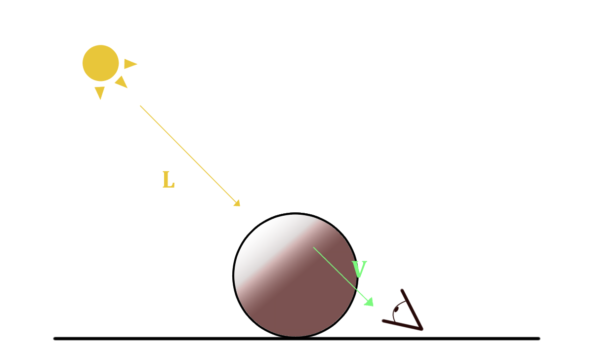
If we look at the simple situation of a directional light casting rays to our object, we can notice that the non lighted region should be dark for an opaque material.
However, for translucent materials this is not the case and this area should be lighted somehow.
The trick to take into account this phenomena is to create a fictive light contribution from the opposite direction of the incoming light.
First, let’s suppose that the incoming light from L is not deviated inside the material, that means that a viewer will best see light rays that go through the object if his gaze is aligned with L and on the contrary if it is orthogonal, he/she won’t see light. This means that the intensity of visible traversing light is proportional to the dot product of $ V $ and $ L $.
$$ I_{SSS} = clamp(V \cdot L ,0,1) $$
| SSS Off | SSS On |
|---|---|
 |
 |
However, inside the object, the light undergoes some deviation and most noticeably at the object surface. So let’s take into account the deviation of the light rays that occurs when they leave the inside of an object. This can be done using the normal $ N $ and the subsurface distortion $\delta$ that tells how much the normal will distort the light towards an halfway direction $ (N - L) $.
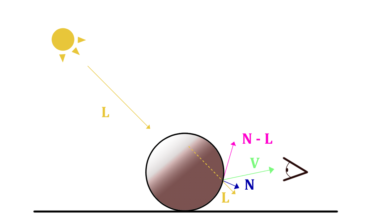
Let’s also give more artistic control to this contribution, tweaking the contrast $ p $ and the scale $ S $with two parameters:
$$ I_{SSS} = clamp(V \cdot - (\delta N - L),0,1)^pS $$
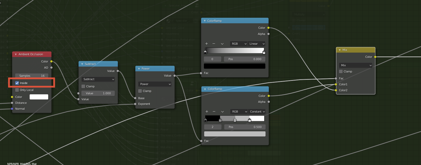
Finally, we can also take into account the thickness of the object light rays are traversing. Indeed, the thicker the object is the more light will be absorbed and restrained inside the object. Hence, the final formula of this approximated SSS taking into account the thickness:
$$ I_{SSS} = clamp(V \cdot - (\delta N - L),0,1)^pS * (1 - thickness) $$
NOTE: Getting the true thickness, meaning the distance that a light ray traversed inside the object, can be costly as its computation is based on ray tracing. Instead, we can rely on a rough approximation using Ambient Occlusion like stated by Alan Zucconi. The trick is to compute AO on the inverted faces of the model, so that we compute the occlusion of the inside of the model and get information of the local thickness which can be sufficient for our case. Thankfully, the Ambient Occlusion node Blender provides this information by checking the Inside option.
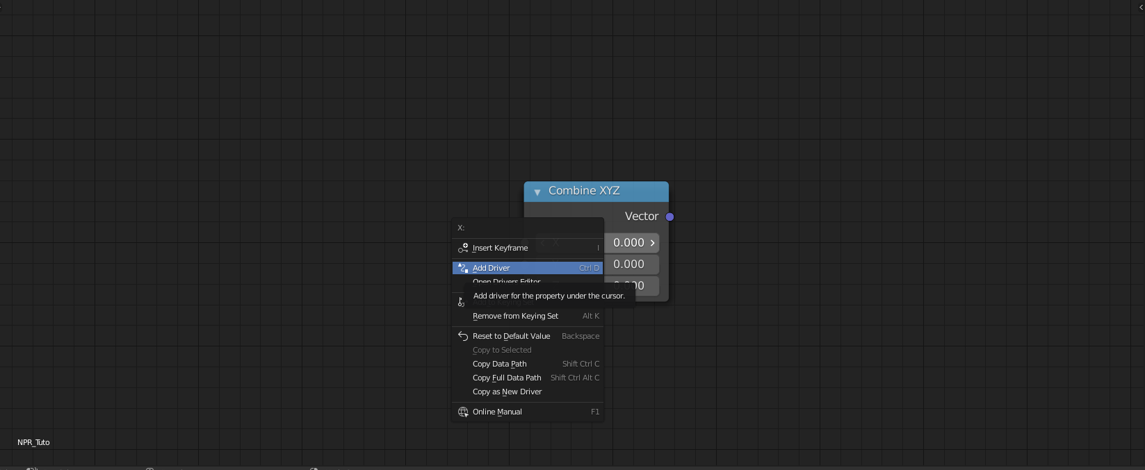
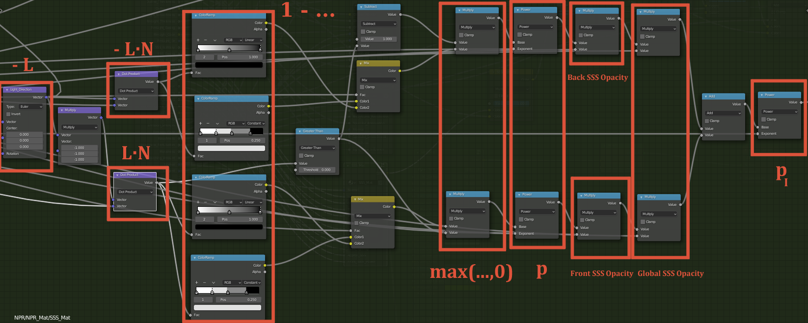
Now that I explained the theory behind this version of SSS, it is time to implement it inside Blender. One difficulty we encounter here with the node system, is the fact that we do not have access to the light direction $ L $. Thankfully, there is a way to overcome this issue using Blender Drivers which are basically linking scene properties to variables inside the node editor. However, it is important to note that SSS will only work for a unique light source and will not be taken into account for others, if you have any on your scene.
To get $ L $ from our main directional light we will add a CombineXYZ node and right click on the x coordinate and choose ‘Add Driver’:
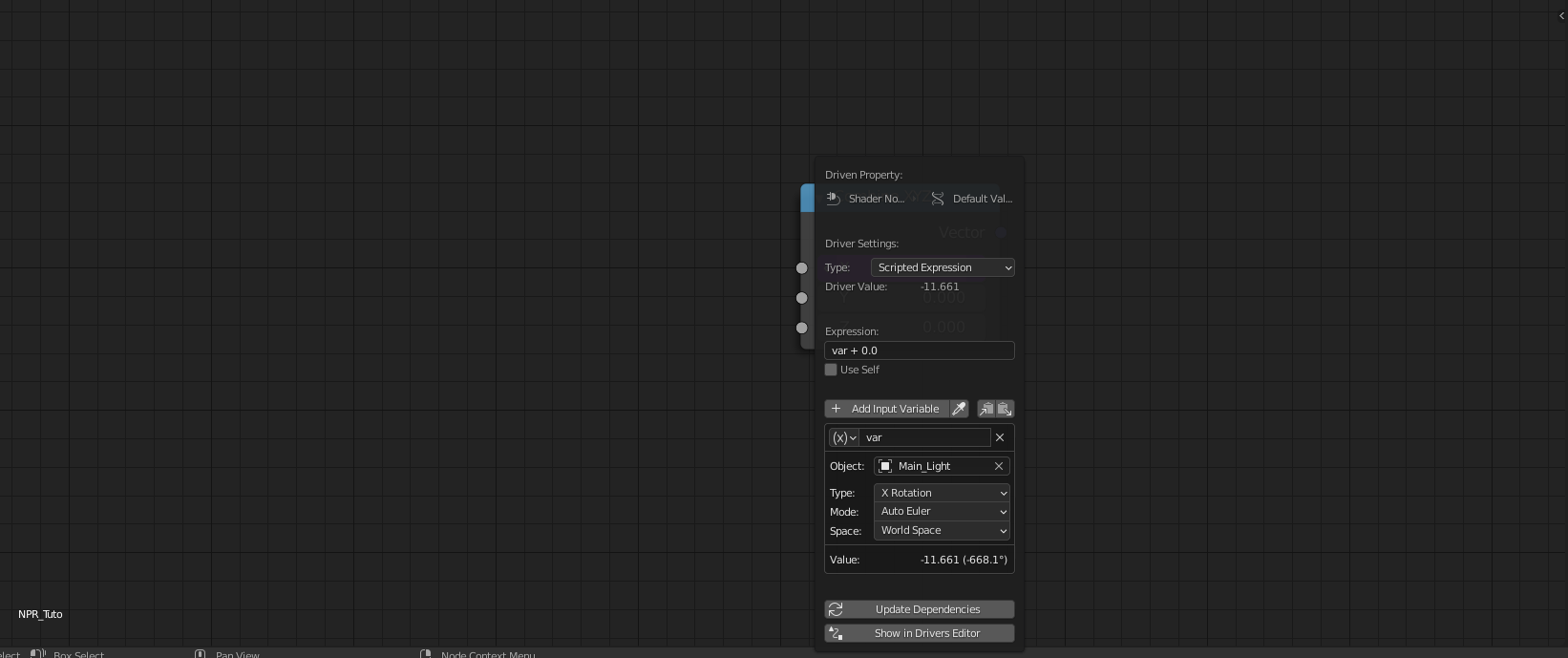
Then, a panel will appear that will allow you to choose the scene property that will be linked to this coordinate. Select your light source in the object field and choose its X rotation as we deal with a directional light (could be the position for a point light).
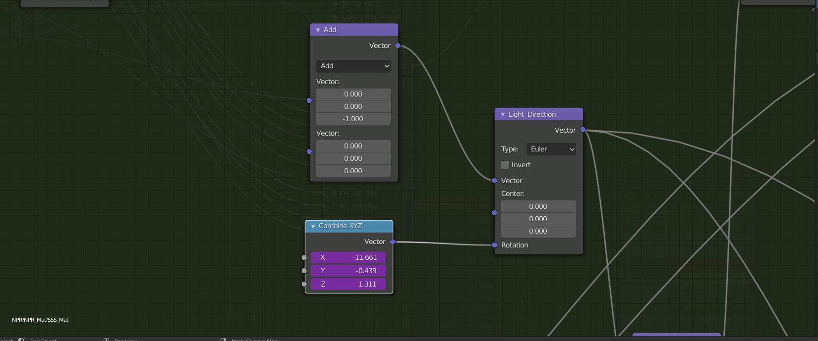
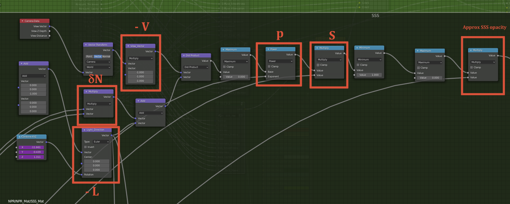
Repeat this process for the y and z coordinates and you get the rotation of the light inside this node. Now let’s convert this rotation into a direction vector. The Vector Rotation node Blender provides does exactly what we need, it applies a rotation to an input vector from the Euler angles (that we retrieve with the Drivers). Notice that the z coordinate of the input vector is $ -1 $ so that we get $ -L $ directly from the rotation node.
We finally compute the dot product with the view Vector $ V $, apply the scale, thickness and power factor and get our approximated SSS contribution.
Inverse Diffuse Lighting
It is possible to go further in the stylization of SSS by adding an additional effect which is much more “artistic” than the approximation I just described. The main idea is to add the complementary of the diffuse component as a contribution in order to make non lighted areas pop out a little bit. The contribution is divided into two parts : front inverse diffuse and back inverse diffuse. The first adds the complementary of the incoming light while the later adds the complementary of the light coming from the opposite direction.
Mathematically speaking :
$$ F_{SSS} = 1 - max(L \cdot N,0) $$ $$ B_{SSS} = 1 - max(-L \cdot N,0) $$
In the same manner as for the approximated SSS, we can add more control to these contributions :
$$ F_{SSS} = (1 - max(L \cdot N,0))^p*\alpha_{front} $$ $$ B_{SSS} = (1 - max(-L \cdot N,0))^p*\alpha_{back} $$
And finally, the thickness of the object should also be taken into consideration:
$$ I_{nverse Diffuse} = ((F_{SSS} + B_{SSS})S)^{p_i} (1 - thickness) $$
Final SSS Node Group
The final SSS contribution results in the sum of the approximated SSS and the inverse diffuse contribution.
$$ SSS = (I_{SSS} + I_{nverse Diffuse})*(1 - metalness) $$
As metallic materials cannot be translucent, we take into account the metalness of the material with a Multiply node and nullify the contribution of the SSS if the material is a metal.
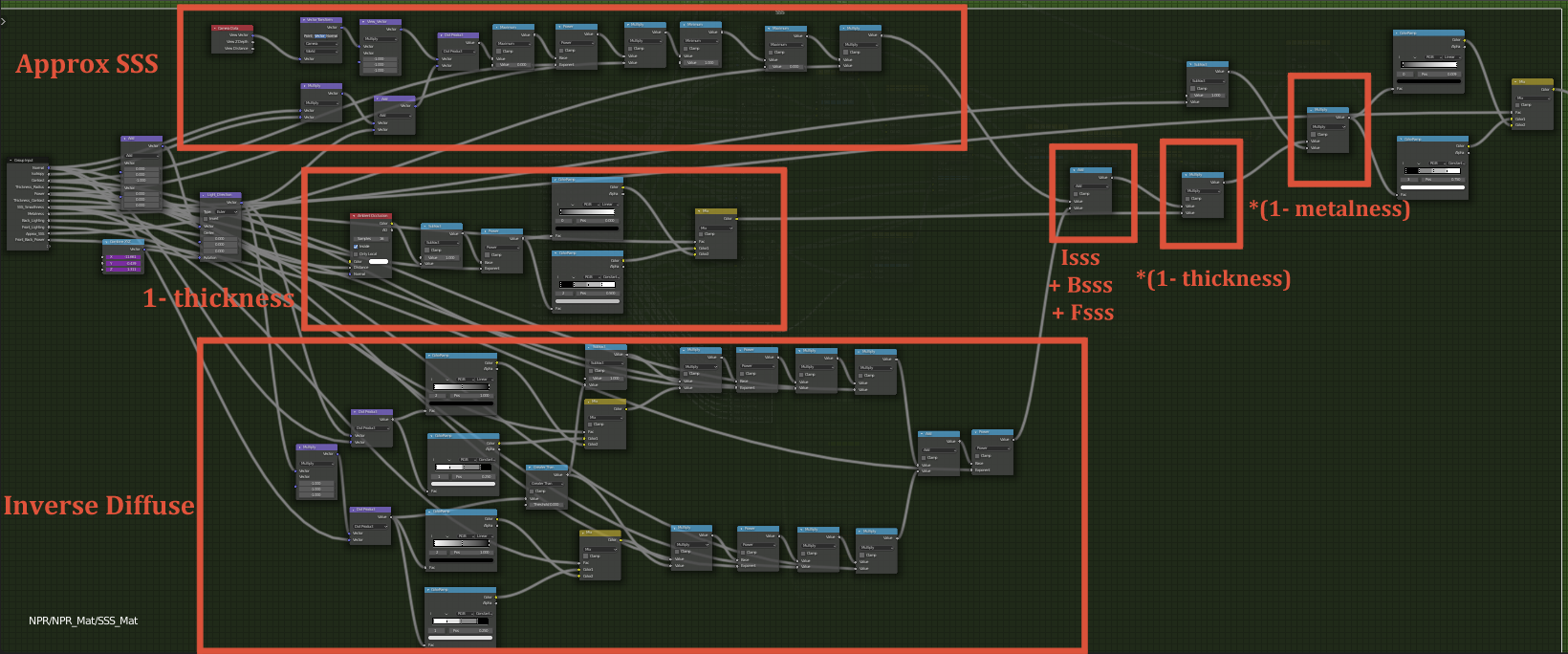
Notice that eventually tweak the final result with color ramps to discretize or smooth the contribution.
Blending Components
Now that we computed all the 7 different contributions, it is time to blend them together. Diffuse, Specular and SSS components should be added together. However, we first apply the Ambient Occlusion to the Diffuse component in Overlay mode in order to increase the contrast between the non occluded and occluded regions. We then proceed to the SSS coloring using a simple multiplication with the SSS color. Note that, at this stage, we could decide to take into account the influence of the material color over the SSS output color. We then successively add the SSS and the Specular component with an Add node.
Finally we add the Rim lighting using a Mix node so that it goes on top of all the other contributions and re-iterate this operation for the Outline that also goes on top of the Rim light.
Et voilà ! We implemented our first NPR shader inside Blender !
NOTE: This way of blending contributions together is one of the infinite possibilities you can test. There is no true way to blend these contributions together as we deal with NPR, so tweak these blend modes to your heart content !
Limitations
The main limitation of the shader is that it only supports one light for the main lighting and the SSS as we use drivers. If you want to add more light I recommend that you use point, spot and area lights even though the SSS won’t be computed for these additional lights. Additionally, Inverse Diffuse Lighting can produce artifacts when it is not properly aligned with the Diffuse contribution, and that is because we compute it as the complementary of a fake Diffuse component. This part should be fixed and take into account the output of the true Diffuse component instead.
There is not too much room for stylizing metallic materials with this shader, it mainly depends on the environment map you use. This aspect can surely be improved a lot.
Finally, we did not cover the artifacts that are due to the topology of the model that may not be adapted to cartoon/anime style, I’ll be definitely working on that part.
Going further ?
From that point, I strongly encourage you to test this shader in more complex scenes like the one below. Do not hesitate to try variations, new ideas often come from testing !
| Sakura Tree 1 | Sakura Tree 2 |
|---|---|
This tutorial only covers the basics but you may want to go further and include texture effects like cross hatching, stippling and watercolor. These effects may rely on noises that will disturb contributions by a small amount. Of course, more advanced methods outside the scope of Blender exist like our post processing method we introduced in our paper. As for the Watercolor and other painterly looks, you can definitely check the tools proposed by Artineering !
You may also go further in shading control and tweak the normals of your model to get rid of unwanted artifacts. Indeed, if you want to go for anime style, unless you adapt the topology of your model to have sharp transitions and add/remove some shadows, you will have to tweak the normals. Inside Blender, you can edit your normals or you can use proxy objects to achieve a more consistent anime look. That is the topic of other tutorials you can find on the Internet but as a good start you can check the Guilty Gear GDC conference that gives a good insight on how to achieve anime looking style in 3D.
There is a lot more to be discovered in that field of course, never stop exploring !
Tutorial Files
You can find this tutorial NPR material inside this blend file as well as the file generating the teaser image here